How Astable Multivibrator Circuits Work
A multivibrator is an electronic circuit used to implement a variety of simple two-state [1] [2] [3] devices such as relaxation oscillators, timers, latches and flip-flops. The first multivibrator circuit, the astable multivibrator oscillator, was invented by Henri Abraham and Eugene Bloch during World War I.
astable définition C'est quoi
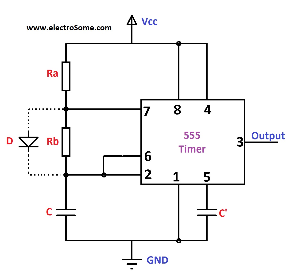
Astable multivibrator is also called as Free Running Multivibrator. It has no stable states and continuously switches between the two states without application of any external trigger. The IC 555 can be made to work as an astable multivibrator with the addition of three external components: two resistors (R 1 and R 2) and a capacitor (C).

BJT astable multivibrator frequency increasing with voltage Electrical Engineering Stack Exchange
Example 1. The Astable Multivibrator The first example is an astable multivibrator shown by its conventional circuit diagram in Figure 8-1. The idealized wave forms on the collectors and bases of transistors Q1 and Q2 are shown in Figure 8-2. At time t0 transistor Q1 is in saturation, and its collector voltage is close to ground.

Astable Multivibrator (using opamp) Explained YouTube
The Op-amp Multivibrator is an astable oscillator circuit that generates a rectangular output waveform using an RC timing network connected to the inverting input of the operational amplifier and a voltage divider network connected to the other non-inverting input.
Solved RI 555 Timer R2 Output Astable Multivibrator 5 01 uF
What is the max. oscillation frequency of this Astable Multivibrator circuit? Is it directly related to transition frequency of the transistor? I plan on using it with BC547B transistor. The hardwired capacitors are 100pF or 1nF, potentiometer is 100kΩ.

555 Variable Duty Cycle, Constant Frequency Astable Multivibrator Multisim Live
555 Astable Multivibrator Calculator #1 This calculator takes R1 resistor, R2 resistor and Capacitor C as inputs and provides frequency and duty cycle as outputs. Resistance (R1) in K-Ohm (Input-1) : Resistance (R2) in K-Ohm (Input-2) : Capacitance (C) in µF (Input-3) : Frequency of AMV (output-1) : Duty Cycle of AMV (output-2) :
555 Variable Duty Cycle, Constant Frequency Astable Multivibrator Multisim Live
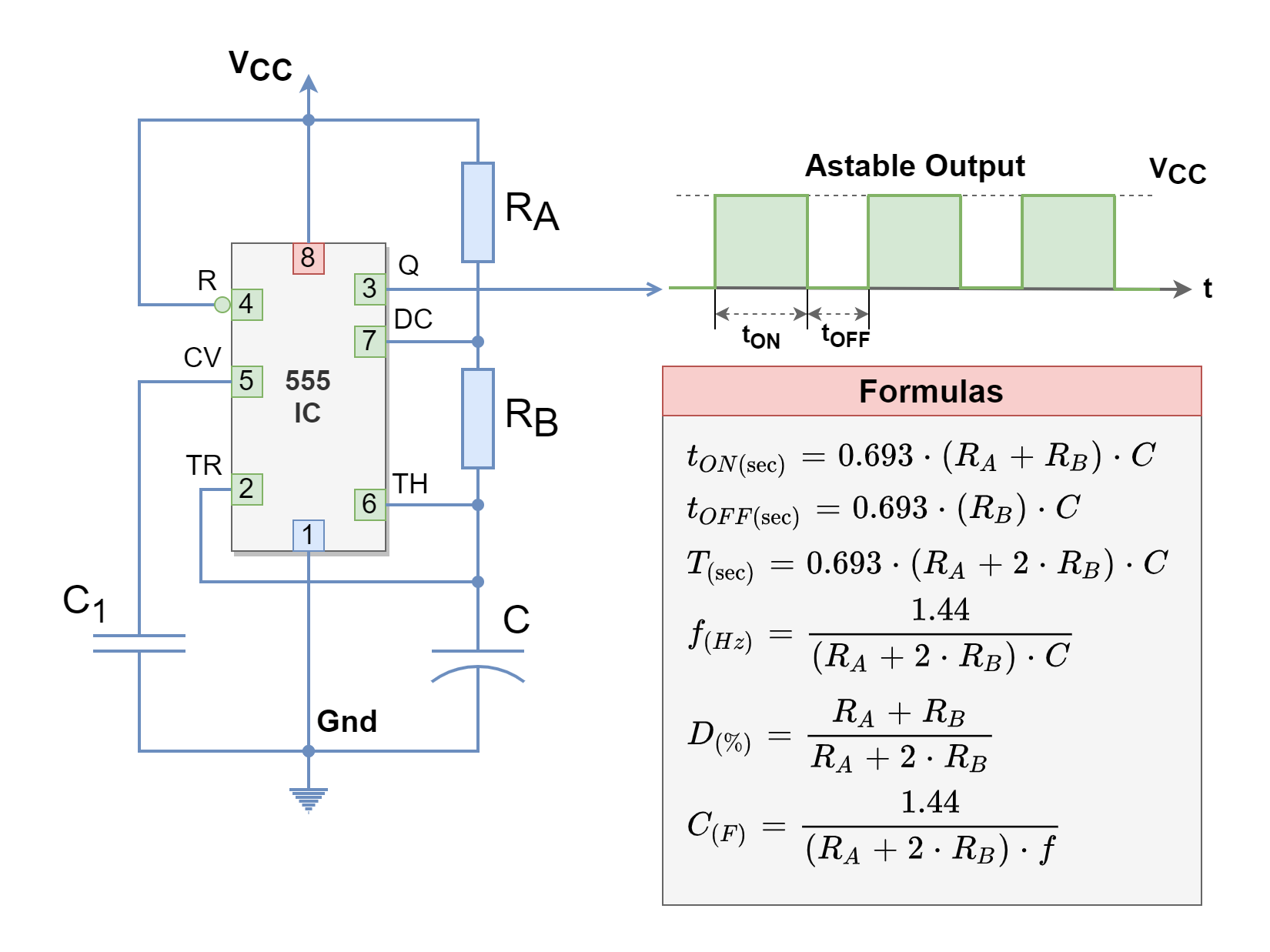
Frequency of Oscillations The ON time of transistor Q 1 or the OFF time of transistor Q 2 is given by t 1 = 0.69R 1 C 1 Similarly, the OFF time of transistor Q 1 or ON time of transistor Q 2 is given by t 2 = 0.69R 2 C 2 Hence, total time period of square wave

Adjusting Frequency of an Astable Multivibrator Skinny Research and Development
A voltage-controlled oscillator (VCO) is one in which the frequency of oscillations varies as a function of voltage. The same circuit is also called a voltage-to-frequency converter (VFC) because a given voltage gives rise to a specific frequency. An astable multivibrator is used as voltage-controlled oscillator [see Fig. 7.13 (a) ].

ISF Robotics astable multivibrator mode of 555 timer ic
What Is An Astable Multivibrator Circuit. An astable multivibrator circuit also termed as a regenerative switching circuit, is an electrical circuit that switches between HIGH and LOW states continuously. The output of the astable multivibrator circuit is a square wave that goes on indefinitely. As simple as it is, the astable multivibrator is.

analog Astable multivibrator frequency mismatch Electrical Engineering Stack Exchange
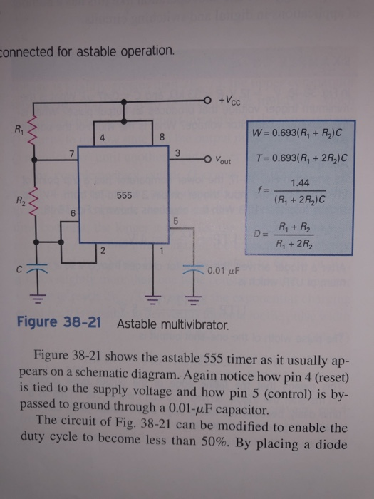
The 555 Oscillator is another type of relaxation oscillator for generating stabilized square wave output waveforms of either a fixed frequency of up to 500kHz or of varying duty cycles from 50 to 100%.
Astable multivibrator calculator
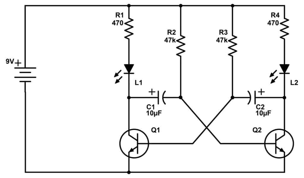
The astable multivibrator circuit is a classic circuit for flashing two LEDs. It doesn't have to flash two LEDs though. It can blink just one LED. Or it can create a tone to play on a speaker. First, let me show you the circuit in action: Astable Multivibrator Circuit demo Watch on Want to know the theory behind how the circuit works?

The circuit is a variable duty cycle, constant frequency, astable multivibrator using the 555
Astable - A free-running multivibrator that has NO stable states but switches continuously between two states this action produces a train of square wave pulses at a fixed known frequency. Monostable - A one-shot multivibrator that has only ONE stable state as once externally triggered it returns back to its first stable state.

Astable Multivibrator Frequency Derivation OPAMP Astable Multivibrator Frequency of
Circuit Explanation The Astable multivibrator consists of two cross-coupled RC amplifiers. The circuit has two unstable states o When V1 = LOW and V2 = HIGH then Q1 ON and Q2 OFF o When V1= HIGH and V2 = LOW then Q1 OFF and Q2 ON In this R1 = R4 , R2 = R3, R1 should be greater than R2 C1=C2
555 Variable Duty Cycle, Constant Frequency Astable Multivibrator Multisim Live
The frequency of oscillation f = 1/ T. Duty cycle is the ratio of ON time (duration of HIGH state or pulse width) to the total time period of a cycle. The duty cycle of an Astable multivibrator = TON/ TON + TOFF. Working of astable multivibrator Circuit. Initially, the voltage across the trigger and threshold input is below 1/3Vcc.
555 Variable Duty Cycle, Constant Frequency Astable Multivibrator Multisim Live
Astable oscillators produce a continuous square wave from its output or outputs, (two outputs no inputs) which can then be used to flash lights or produce a sound in a loudspeaker. The basic transistor circuit for an Astable Multivibrator produces a square wave output from a pair of grounded emitter cross-coupled transistors.
555 Variable Duty Cycle, Constant Frequency Astable Multivibrator Multisim Live
In electronic circuits, astable multivibrators are also known as Free-running Multivibrator as they do not require any additional inputs or external assistance to oscillate.